DIY drone
Introduction
In this article, we will talk about assembling with your own hands a fully autonomous drone, controllable by the ground control station "LOGOS" (hereinafter GCS). Our goal is to demonstrate the assembly of a ready to fly aircraft which executes all flight missions that the GCS offers without using a remote control.
Before attempting to follow the instructions in this article, please make sure there are not restrictions on purchasing or keeping the drone parts, as well as assembling and flying handmade uavs in country or region you are going to do it.
Accessories
For assembly we will need the following accessories:
| Name | Image |
|---|---|
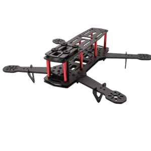
| ZMR250 Quadcopter Frame |
|
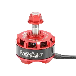
| 4 x Racerstar BR2306S 2700 KV engines |
|
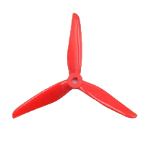
| 2 three-bladed CW propellers 5040 (DALPROP CYCLONE 5040) |
|
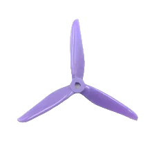
| 2 three-bladed CCW propellers 5040 (DALPROP CYCLONE 5040) |
|
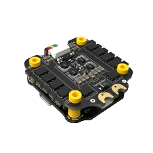
| Flight controller with ESC stack SpeedyBee F405 V3 of 30x30 mm size |
|
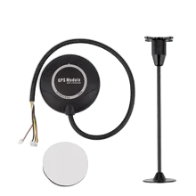
| GPS module with tripod (UBLOX 7M or 8M) |
|
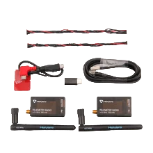
| Set of 2 modems for two-way communication at 100 mW (Holybro SiK Telemetry Radio V3) |
|
| Lithium-polymer battery with XT-60 connector and current from 3500 mAh |

|
| Tape |
|
The SpeedyBee F405 V3 controller was originally designed for remote-controlled flights. And the default firmware from Ardupilot is designed for this too. However, we reprogrammed it a little, which made it possible to connect a telemetry module and make the drone completely autonomous and accept all commands from the computer.
The motors we recommend are different from those showed on photos of this article. The first version of this drone was assembled on the Racerstar. We just didn't have the same ones on hand and decided to demonstrate on similar ones. They made our drone 50 grams heavier in comparison to the first version, which, naturally, will affect the duration of flights.
Tools
Below is the required set of tools:
| Name | Image |
|---|---|
| Soldering kit: soldering iron, stand (3rd hand), solder and chips for cleaning the tip |
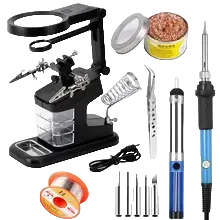
|
| Flux |

|
| Solder sealant varnish |

|
| Small socket wrenches and pliers |
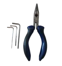
|
Assembly: Part One
First, you need to assemble the lower part of the frame by screwing the red posts as shown in the picture:
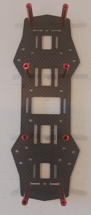
As you can see from the images below, I forgot to do this at the very beginning and paid the price by having to rebuild the frame again in the very end.
Finish the first floor, and install the power distribution board on it in the center, then secure it with the bolts from the flight controller kit. Next, screw on all the motors one by one, wrap their wires with insulating tape at the base of the frame so that they do not dangle. After that, measure the length of the wires, sufficient to be soldered in series to the contacts of the distribution board and cut them off*. Then, strip the ends of the wires to prepare them for tinning.

* Be extremely careful and do not try to find the ideal length of wires the first time. It is better to cut with a small reserve, as it will not interfere much. But it is quite difficult to extend too short wires. Also, do not throw away the cuttings. In the future, they may come in handy if you need to assemble a larger drone on the same motors.
Soldering
Power Distribution Board
First of all, we will solder* the motor wires, then the wires** connecting the power supply to the distribution board, and finally the capacitor***. Solder them according to the scheme on the image:
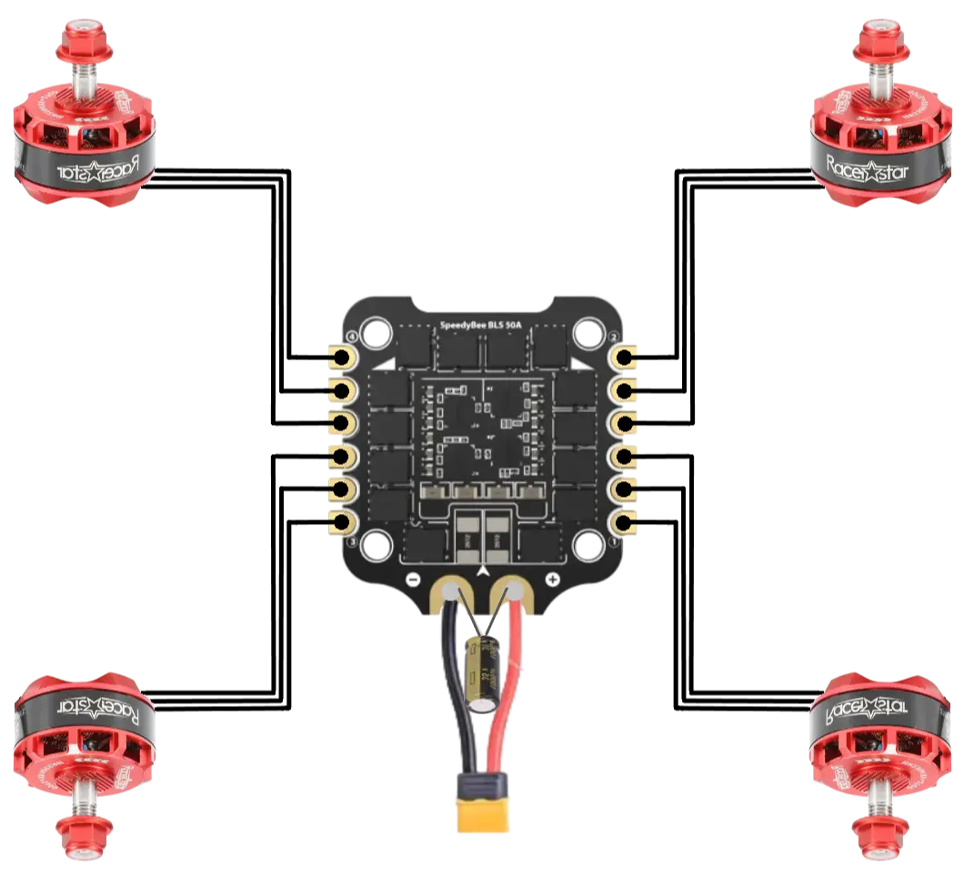
* Don't forget to tin the contacts before soldering: cover the soldering area with flux, then melt the solder and apply it on top of the flux to form a round mound large enough for the wire to be securely attached to it. Repeat the same with the wires so that they "absorb" enough solder. Only then solder the first to the second.
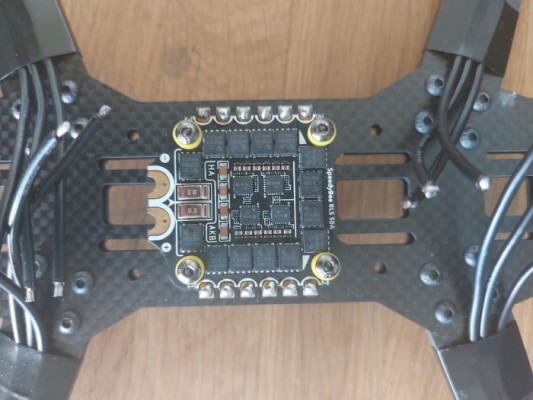
** The red wire of the power supply should be soldered to the "+" sign, the black wire to the "-" sign.
*** The capacitor is needed to smooth out voltage surges supplied to the board from the source. The capacitor has 2 poles. Traditionally, the longer wire corresponds to the "+" sign, but for ease of soldering it is better to shorten it. Do not forget to put the heat shrink tubes supplied in the kit on the contacts before soldering the capacitor.
After soldering, all the places where it was done must be covered with a special insulating varnish and left to dry for the time specified by the varnish manufacturer. You can do it 2 times with an interval of 30-60 minutes just in case.
Flight controller
Next, we need to solder the modem* and GPS module** wires to the flight controller. The soldering should correspond to the following scheme:
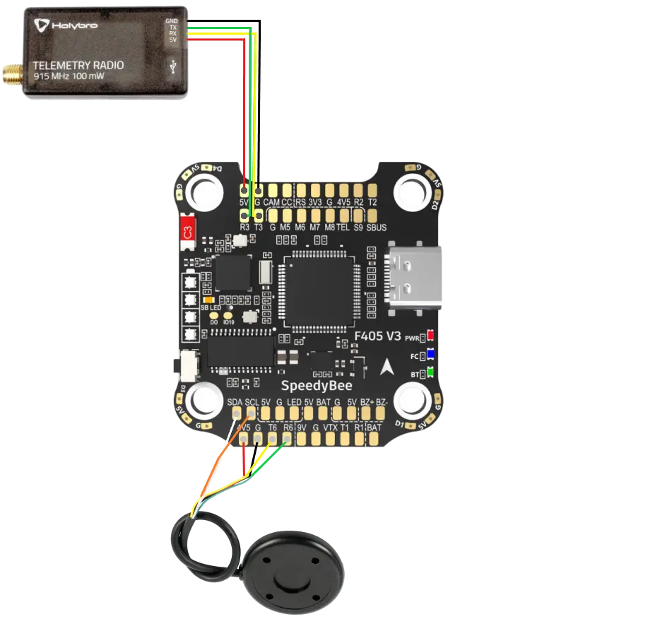
* There are 6 wires coming from the modem. Our controller does not have an interface for RTS and CTS, so we will only solder the remaining 4, and RTS/CTS can be pulled out for aesthetics. Do not throw them away - they may come in handy in the future if you decide to switch to another flight controller supporting RTS/CTS. Follow the instructions below. If you are right-handed, it is easier to solder in the same order.
- 5V -> 5V
- Gnd -> G
- TX -> R3
- RX -> T3
- RTS - don't solder
- CTS - don't solder
Please note that the "Tx" (Transmit) contacts from the modem/GPS module are soldered to the "Rx" (Receive) contacts on the controller. Also, it is necessary to strictly observe the numbering of "T" and "R", since our controller will be programmed to send and receive signals via these specific channels.
** Before soldering the GPS module, you need to shorten the wire to a length approximately equal to the length of the top cover of the quadcopter frame. Also, before soldering, you need to pull the wire through the hole in the cover, as shown in the picture:
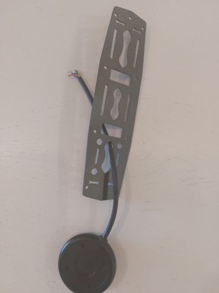
There are 2 groups of wires coming from the GPS module:
- UART + power - 4 wires: Tx, Rx, GND, 5V
- I2C - 2 wires: SCL, SDA
You should solder according to the same logic as with the modem. If you are right-handed, it is easier to follow the order below:
- SDA->SDA
- SCL->SCL
- Gnd->G
- 5V->4V5
- Tx->R6
- Rx->T6
After soldering, all the places where it was done must be covered with a special insulating varnish and left to dry for the time specified by the varnish manufacturer. You can do it 2 times with an interval of 30-60 minutes just in case.
Assembly: part two
Connect the power distribution board to the flight controller board using the 8-pin cable included in the kit:
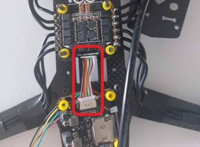
Place the controller on top of the distribution board and tighten it with the plastic nuts provided. If you've done everything correctly, the arrow on the flight controller board should point forward - away from the power supply wire.
Assembly: part three
Now you need to fix the modem on the first floor of the quadcopter frame in its front part. If desired, you can use Velcro, double-sided tape or electrical tape, as you like. For reliability, I used 2 options: first I glued the Velcro, then, after installation, I wrapped the module with electrical tape. This way I can be sure that it stands vibrations, and my drone will not lose connection with the GCS.
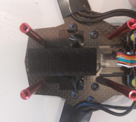
Don't forget to plug the cable connecting the controller to the modem before installation, and also screw the antenna to the modem. This completes the assembly of the first floor of our drone.
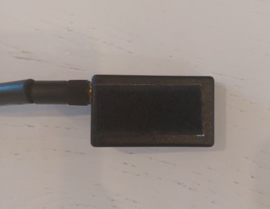
Never power up the modem until you are sure that the antenna is attached to it. Otherwise, it will fail very quickly.
Assembly: Part Four
We need to install the GPS module tripod on the top cover of the frame through which we passed the cable. The module must be on such a tripod, since it also contains a compass. By raising it above the entire structure, we avoid the influence of the magnetic field from the electric motors. If this is not done, the signal from the compass may be incorrect.
We will also need to shorten the tripod stand by 2 times and re-grind the end of the stand on the side where the cut was made. Considering that the tripod is already on the second floor of the copter, the distance should be sufficient. In addition, the GPS module will be subject to a smaller amplitude when the drone vibrates, and this will also make our device more beautiful.
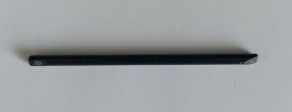
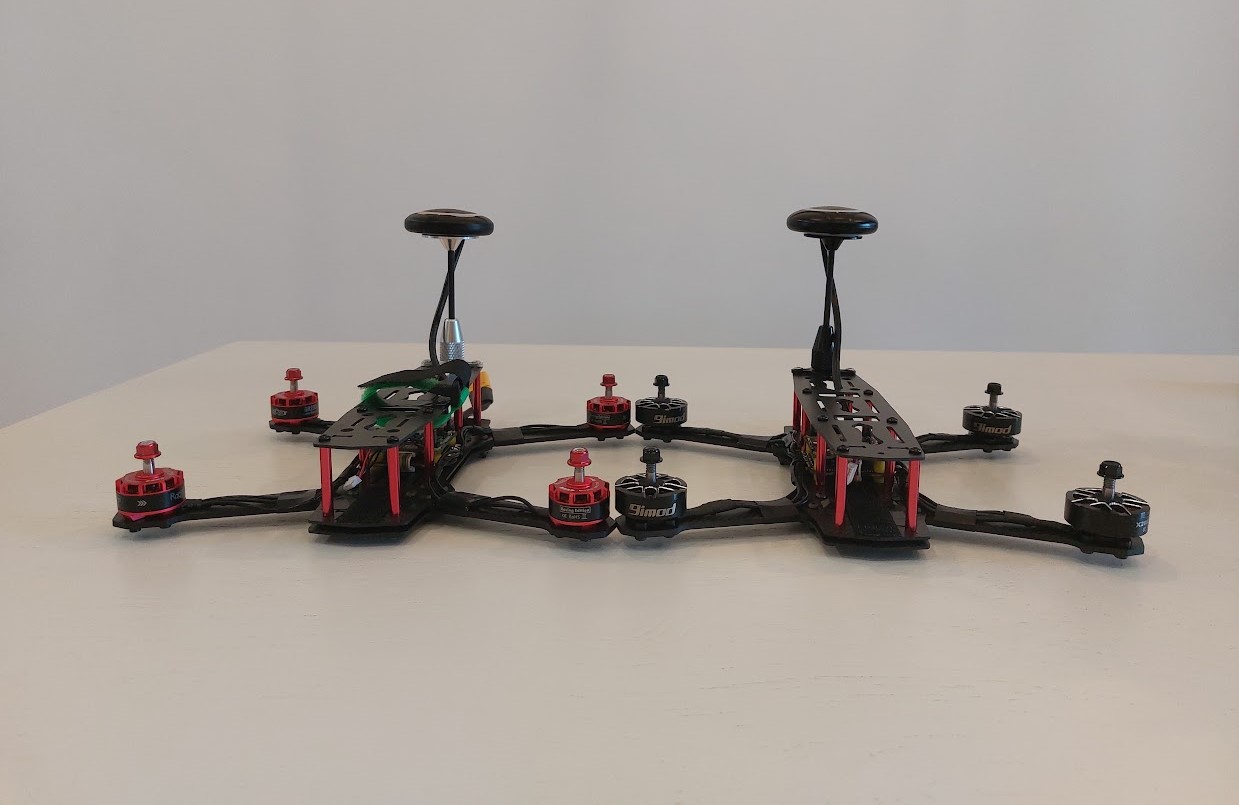
The result after all manipulations should look something like this:
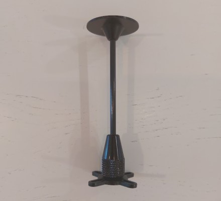
Screw the top cover to the red metal posts, leaving the 2 rear posts near the power supply cable alone for now. Install the GPS module tripod in place of the rear posts. The tripod has 4 mounting points, but we will only need 2 of them, since the manufacturer did not intend to use UBLOX tripods on this frame. The remaining mounts can be left as is for future assemblies, or cut off if desired.
After that, take the double-sided tape of a round shape from the set and stick it on the tripod plate. And stick the GPS module on top of the tape so that its arrow points straight ahead.
Installing propellers
Now we will demonstrate how to properly install the propellers on your quadcopter. But this will be done only to give you an understanding, since it is too early to start flying - you still need to figure out the firmware of the flight controller and settings. Below is an image demonstrating the direction of rotation of the propellers. The image should clearly show that the propellers on the right and left are mirrored and "row" inward from the front and back. This is a mandatory condition, without which you will not be able to fly. As you may have guessed, the different colors of the propellers were not chosen by chance - this makes the installation process somewhat easier. But this is not a requirement.
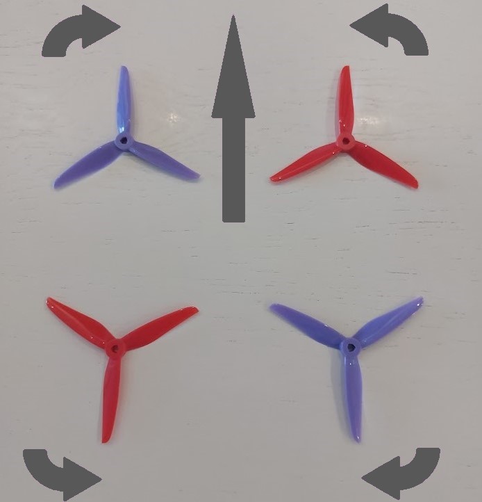
Also, it is too early to install propellers on your quadcopter, because we have to flash the flight controller with the firmware, then calibrate the accelerometer and compass, and make sure the motors rotate. All this should be done without propellers to avoid injury. Propellers should be screwed on at the very last moment - just before the flight.
At this stage, the drone assembly can be considered complete. The next article will tell you how to flash the flight controller.
Date of publication: 15.08.2024
Author: Valchuk Alexander
Interested in drones?
Professionals at AEROLOGOS are actively developing software for the ground control station for UAVs. We have developed a solution that is useful for both businesses and amateurs of unmanned vehicles. You can find out more about our GCS clicking on the following link: